PRODUCTS
PROJECT: Conveyor Real-Time Diagnostic System
A major car manufacturer had a persisting problem of very costly conveyor down times. The technology available then would only monitor the pull (Fz) in the conveyor. Measured values were stored in a memory chip on board for later download. Hence this technology would only be able to capture the value after failure occurs. More often conclusions by that technology were not accurate. It was found that most conveyor failures are due to bending moments rather that the pull in the line. Solution: SensorData developed a turn-key system consisting of a 4-component link shaped wireless sensor, a remote transceiver, and processing software. Dynamic forces (Fz, Mx, My, Mz) measured by the sensor are wirelessly transmitted to the tranceiver. A computer with residing software processed the forces, calculated the resulting combined stresses, and compared instantaneous combined stresses with predetermined maximum allowable values. Because critical parameters were monitored in real time, it was possible for the first time to predict and mitigate a failure before it takes place.
Two US patents were obtained on this system.

Sample of the data collected by the SensorData’s Conveyor Real Time Diagnostic System
PROJECT: Conveyor Track Wear Monitor System
Expensive conveyor downtimes are usually attributed to either excessive force due to component mal-function, or to track excessive wear. Usually track wear was measured manually by calipers at different locations. Access to these locations is understandably cumbersome, dangerous and very time consuming. A major auto manufacturer commissioned SensorData to develop a system to automate this process.
Solution: SensorData developed an automated laser profile measurement system. The system accurately records profiles of conveyor track flanges (prone to wear) at as many predetermined locations as needed and stores these profiles into memory cards. At the end of one full turn of the conveyor, data is retrieved and analyzed by a specially developed algorithm identifying areas of normal, marginal and excessive wear.
What used to take several days of measurements the traditional old way, now hardly takes minutes (the time to complete a full conveyor cycle) thanks to this state of the art technology development. One can imagine the tremendous time and cost saving of this system.

Data sample from a simulated conveyor track wear
Project: Connecting Rod Bolt Loosening

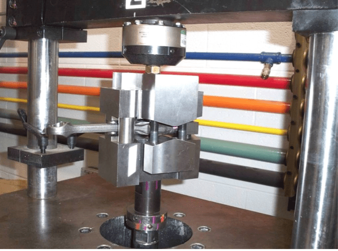
Self-loosening test rig installed on a hydropulsator
MAHLE Industries Inc, Farmington Hills, MI Copyright © 2010 SAE International
A German automotive component manufacturer experiencing bolt loosening of some connecting rods was referred to SensorData for help.
Solution: After studying the possible causes of the problem, our engineers identified the most probable ones and designed some complicated fixturing tools to reproduce the loosening phenomena. The most likely culprit was buckling and/ or bending of the connecting rod. Once the loosening was consistently reproduced; it was easy then to eliminate it.
The early phases of this study were done using the transverse vibration loosening machine developed earlier. Then after the fixturing routine was developed the actual tests were done on an MTS fatigue testing machine.
A US patent was obtained as a result of this work
Project: Unique 3-Component Load Cell

Usually a 3-component load cell is a load cell that measures loads in three perpendicular directions. The uniqueness of this project is that this load cell is required to measure three unique forces in the same direction accurately.
Volkswagen wanted to measure the disengage force on one of their clutches. The disengage force is applied through three spring loaded leavers. Required was to find the force carried by each leaver. The lateral space was not to allow a standard load cell height, let alone to allow three of them to measure each leaver force separately.
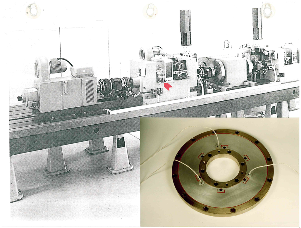
SensorData engineering in collaboration with VW’s, came up with a special design (link to VW_Textar) that fitted into customer’s elaborate test rig shown.

