FREQUENCY RESPONSE: The Key Specification that's often overlooked
One may wonder if this discussion has anything to do at all with force and /or torque sensors, however with little patience, not only some ambiguity will be removed, but also some very decisive eye-openers will be revealed when considering a sensor for an application.
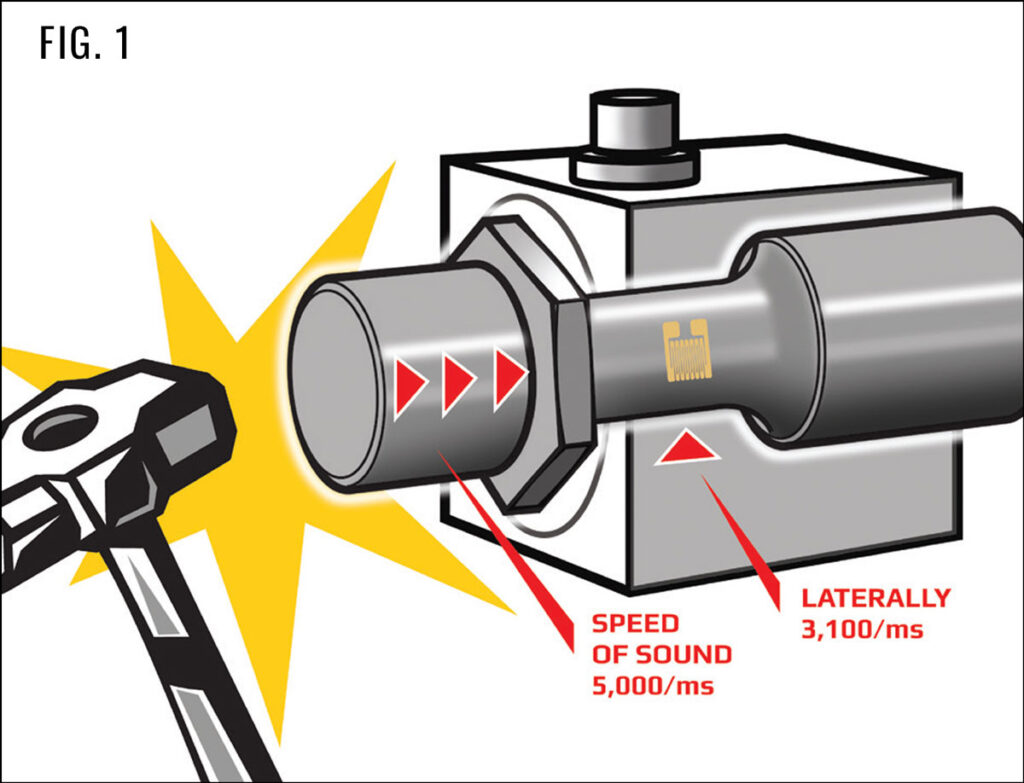
The schematic (FIG. 1) is a simplified yet very accurate representation to what happens in a sensor, from the moment an event (e.g. impact force) is applied to the sensor till this event shows up on an indicator.
The event (the impact) causes a stress wave that travels in the sensor at the speed of sound longitudinally (at 5000 m/s) and laterally (at 3100 m/s) to reach strain gauge locations.
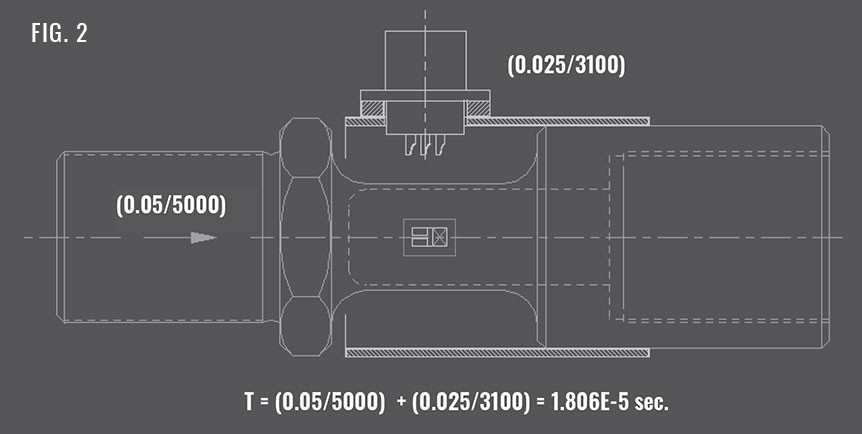
Assuming a sensor 10cm long, and 5cm diameter, gauges are in the middle of the sensor, then time “T” for stress wave (event) to reach gauges;
T=(0.05/5000) + (0.025/3200) = 1.806E-5 sec. (FIG 2)
i.e. this sensor can respond to a signal frequency 1/T = 55,357 Hz
For all practical purposes, any simple sensor (a Wheatstone bridge of strain gauges on a piece of metal) can translate the mechanical energy of an event into proportional electrical energy in almost no time
NEED A QUOTE?
We love helping our clients excel. We are happy to discuss your sensor requirements and provide ideas on how you can become more competitive, productive and profitable with SDT products.
We love helping our clients excel. We are happy to discuss your sensor requirements and provide ideas on how you can become more competitive, productive and profitable with SDT products.